Drone Escort Robotics Project
Summary
Our project was to have one drone maintain a constant distance above and behind another drone moving along a predetermined path. Due to the limited time, we used the drone’s built-in PID position control that could take X, Y, Z and YAW inputs and would move the drone toward that position. I was responsible for creating the algorithms that determined the target position of the Following drone. Collision avoidance algorithms and a second-order prediction influence the target position allowing us to reduce the position error caused by latency in the communication and PID control system. Through testing, we were able to show that the following drone could accurately track the user-controlled drone even if the straight line path of the following drone went through the user-controlled drone. A new control algorithm that would allow for a stiffness-based controller for position, velocity and acceleration would be an improvement that can be made by modifying the drone firmware.
Pathfinding Algorithm
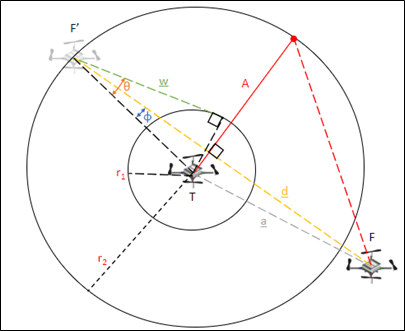
I designed a control algorithm, created a vertical cylinder around the tracking drone and moved the following drone to avoid it. There were 3 main operating conditions of this program:
- The drone is within the minimum radius in the X-Y plane
- The drone moves along the shortest path to get outside the minimum radius
- The drones path goes through the minimum radius in the X-Y plane
- The drone will detour around the minimum radius
- No obstructions
- The drone will move toward the target point
Controller Design
I designed the controller to take advantage of the PID position controller built into the drone, as we needed more time to implement our own controller. This control method resulted in us using the controller below, where half runs in our Python script and the other half runs on the drone.
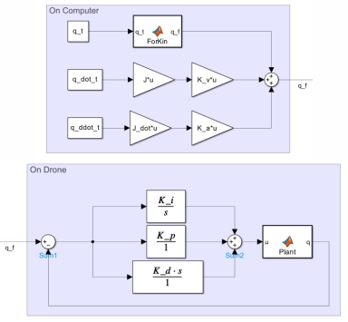
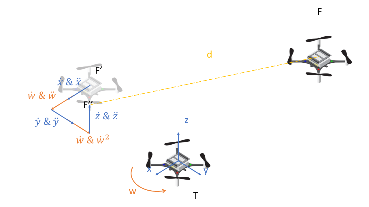
Since the controller was only a position-based controller and the point we were attempting to follow was a moving point, I added a stiffness matrix for the velocity and acceleration of the target point that would add onto the target point sent to the drone, as shown in the diagram below. This stiffness controller allowed us to send the drone to a point we expect the target point to go through, reducing the steady state error of a point with a non-constant velocity and acceleration.
This stiffness controller decreased the steady state error of a function with a sinusoidal acceleration by 30%, as shown in the figure below.
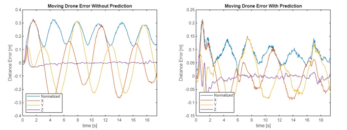
We only tested this program with an actual flying drone, but using a simulated path for the tracking drone would allow for easier tuning of the control algorithm. We expect to drop this error even further with more fine-tuning of the stiffness matrix and a better smoothing method on the velocity and acceleration.
Code
This repository contains all the code required to implement our system on your machine.
Report
This report we wrote for the project has a more in-depth explanation of everything we did for the project.