UBC Capstone
Summary
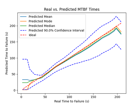
This project was a case study performed on behalf of Fujitsu AI Technologies, looking into implementing a Predictive Maintenance system. Predictive maintenance involves looking at the operating conditions of a system and using an AI model to predict when it will fail to allow you to schedule maintenance before the device fails. We implemented this on a small $80 air compressor as it is easy to fail and cheap to replace. We chose six sensors that monitored the compressor’s voltage, current, pressure, sound, temperature, and motor speed. Through researching reviews, we chose to analyze a failure when paint builds up in the valves resulting in pressure dropping. We recorded data on the compressors running normally and then in an environment with aerosolized paint until they failed. We fed the data from the compressor failures into an LSTM machine-learning algorithm that outputted the predicted failure time as a probability distribution. We ran data not used in training through the model to benchmark the effectiveness of our model, and it’s shown in the plot below. This plot compares the predicted time to failure to the actual time to failure and shows the confidence intervals converging through the blue lines.
My Major Contributions
Sensor Selection and Wiring
One part of the project I was in charge of was researching different sensors and implementing them so we could log them through our LabJack DAQ. I compared different sensors for each physical quantity we wanted to measure and compiled a list of sensors that would be able to measure each of the quantities we needed to.
| Physical Quantity |
Sensor | Justification |
|---|---|---|
| Sound | Contact Microphone | Can easily be mounted to the inside of the compressor to measure vibrations without being saturated by airflow. |
| Rotation Speed | Contactless Rotary Encoder | The one selected can be mounted to any shaft diameter easily. |
| Current | Contactless Current Meter | Easy to install and won't impact the voltage. |
| Voltage | Custom Voltage Divider | Cheap to implement and Accurate. Used custom Protection circuit. |
| Temperature | Thermocouple | cheap, high Temperature range and supported by the DAQ. |
| Pressure | 100A PSI Transducer | Small and temperature resistant allows mounting inside the compressor. |
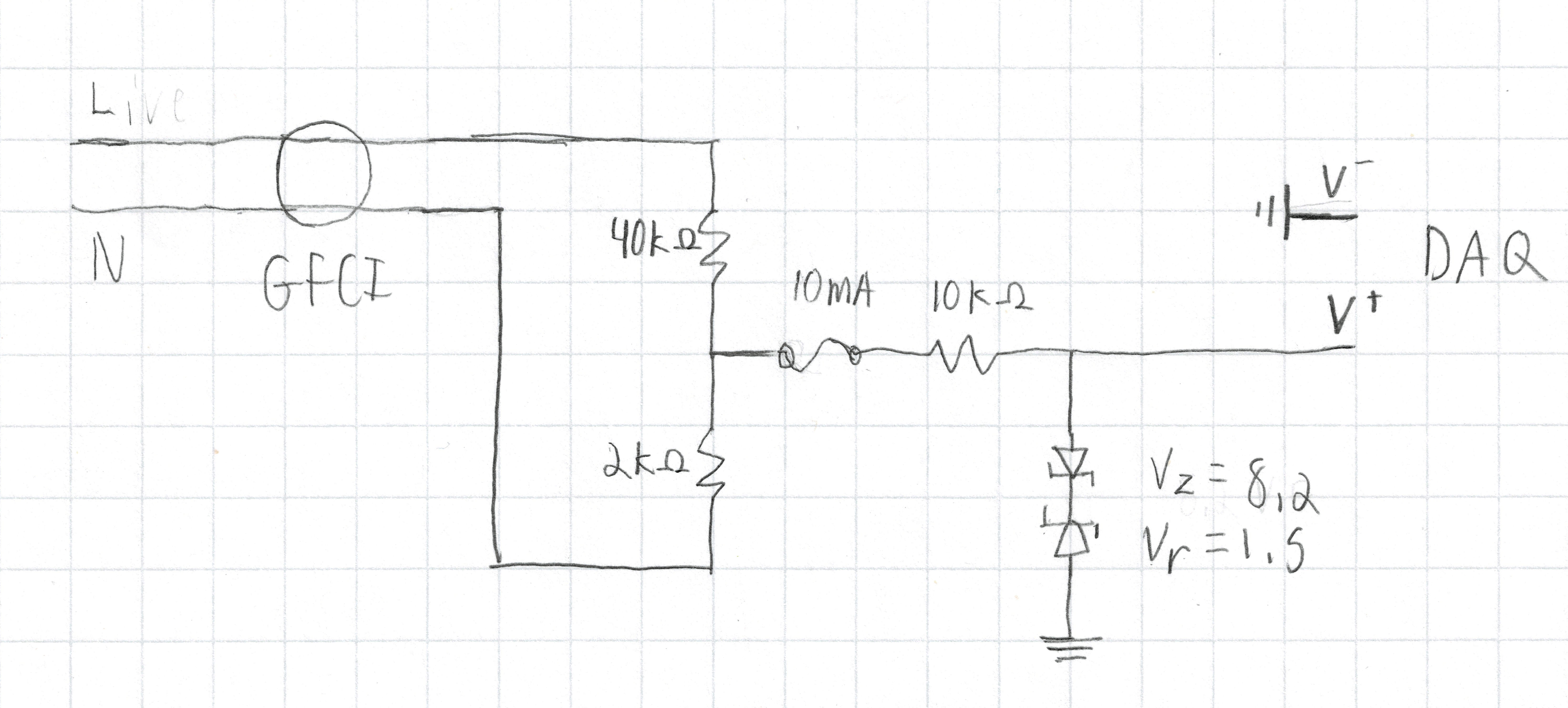
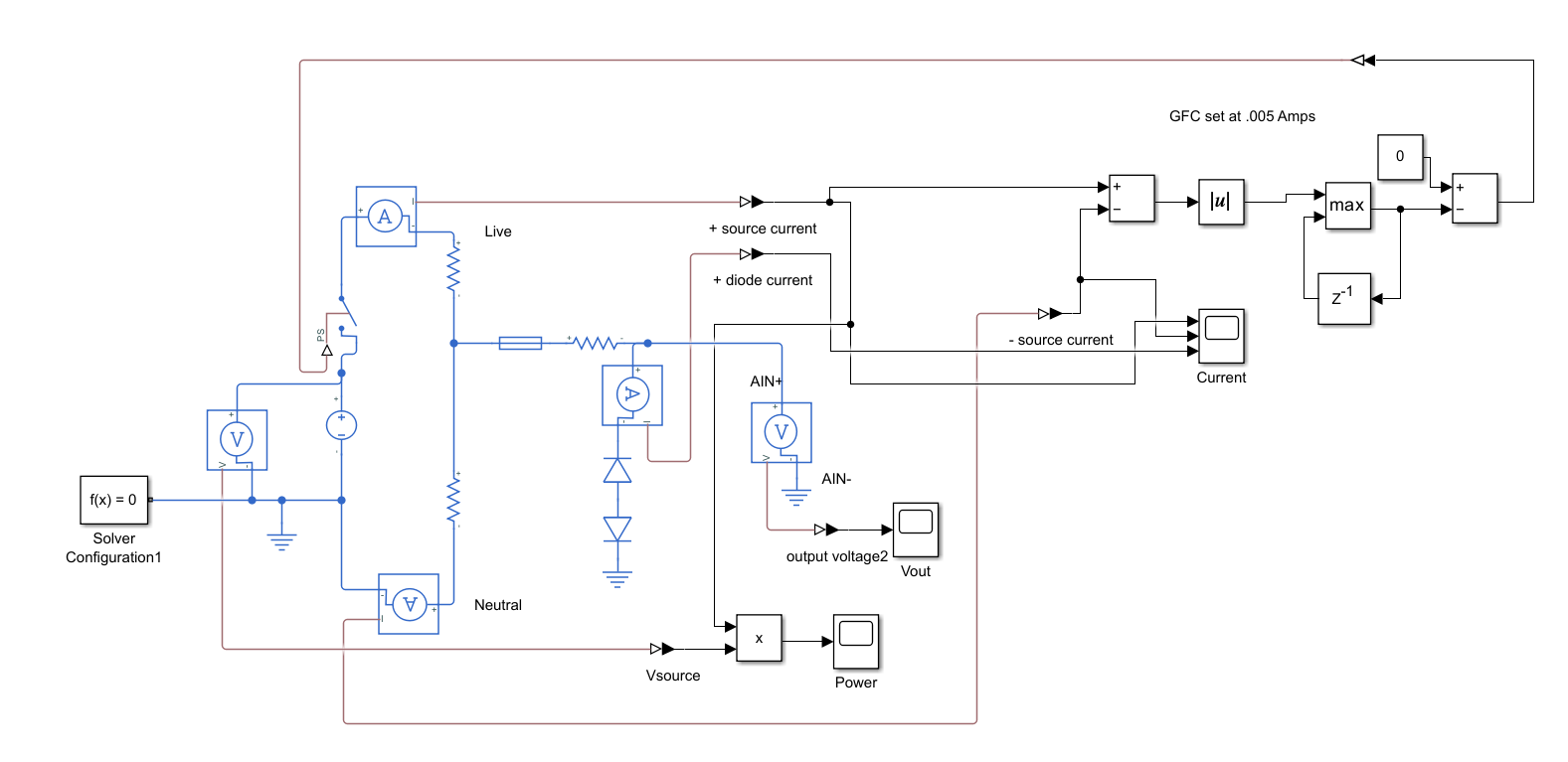
For the voltage sensor, I had to design a custom voltage divider that scaled a 170Vp-p sinusoid to an 8Vp-p sinusoid that was within the +/-10V the DAQ could read through my research and consultation I came up with a design that was cheap, easy to manufacture and safe to the end user. I designed the circuit to be short-safe, over-current safe and over-voltage safe using Zener diodes and fuses. This voltage protection also made it safe for human users but was coupled with a GFCE outlet to guarantee no risk to the end user.
Data Recording and processing
The data script I created automatically imported and stored everything in an SQLite database that is accessed later for training and validation. The data recording script’s main features and a link to the script are listed below. There were several improvements that I wanted to make to the script, but due to the tight schedule, once I got it functional, I had to move on to other tasks.
- Full Configuration
- Fast and slow recording frequency
- Channel configurations (thermocouple, quadrature, etc.)
- Digital output control
- Records sound through a USB DAQ
- using FFT transforms makes the data asynchronous, so synchronization between the LabJack and Line-in
- Allows recording sound continuously and accurately without using half the LabJack DAQ’s processing power.
- Storing all the raw data
- instead of processing, it allowed us to alter the method of processing the data so we could determine the method that would be best to process.
- Dual speed logging
- Records fast data for a period, then takes a single averaged measurement before returning to fast data logging
- allows recording kHz speed of specific sensors like voltage and current but keeps the temperature at sub Hz.
- Acceleration Control
- since our project needed the opportunity to accelerate wear, the logging script has a flag that enables a duty cycle-controlled output.
- it would also include a flag in the data that lets the processor know when acceleration is applied